13 - Textures & Materials
The next few chapters we will rely on each other. They are all about how Unity renders the image to the screen. We will start with Textures and Materials as they build the foundation. They are a tightly intertwined concept, as textures are actually additional information the shader processes to calculate the final pixels.
You will often see shaders and materials used in interchangeably. Yet they are different things. The material is the artistically exposed part of the shader and what we apply to any given Gameobject. The shader is the underlying math the GPU processes to calculate the desired look. Inside a material you can switch between different shaders. You can even write shaders yourself. The Unity HD Renderpipeline even offers a visual scripting tool for shaders.
To provide this additional information 2D images are wrapped around an 3D object along its UVs. These UVs are either standards defined in primitive objects, or need to be pre-defined in the 3D software in which the object was created.
Once we apply the textures they can define an entire range of information. Simple unlit shaders will use just the color information. “Physically Based Rendering” shaders use different textures to affect how reflections are rendered, to add faked depth detail in the object or even define areas that are supposed to be emitting light. Textures are a major factor in creating photorealism. But they are also what drives the beautiful hand drawn styles you see in some games.
But! Textures are a thing we pretty much only apply in Unity. We handle the creation of textures in other software packages.
Setting up Textures
To use textures in Unity, we first need to import them. Then create a material and apply it to an object. If you select the material in the Project View, you see all of its inputs in the inspector.
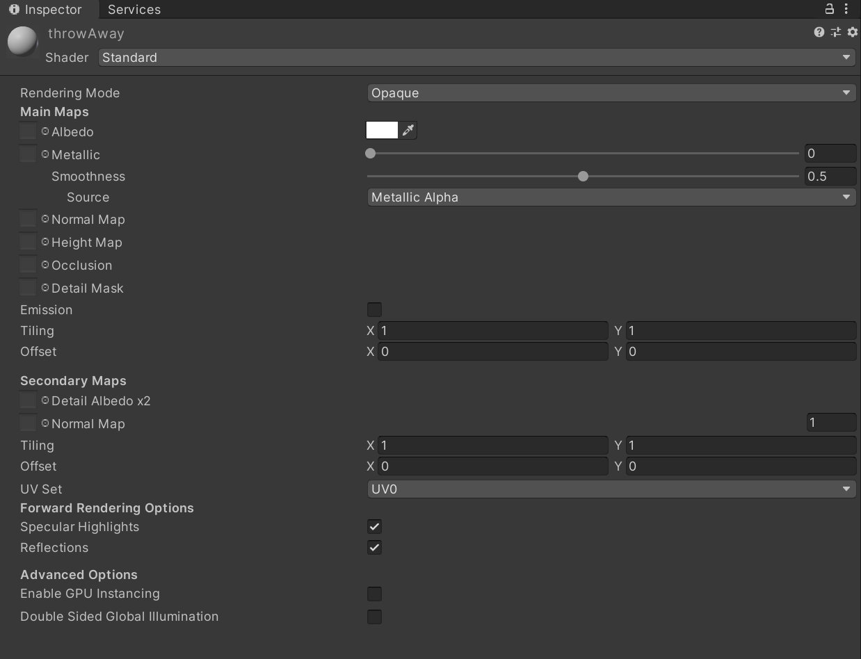
Material Inspector
For now, we will create a simple PBR floor. Create a fresh material inside Unity. At the top of the material component you can select the shader. By default Unity will offer the “Standard” shader and that is what we will be using. The next thing you need to create PBR Materials are PBR Textures. These are texture sets that typically comprise a diffuse/albedo, metallic, roughness and normal maps. Each of these serves a specific purpose in rendering. There are several ways of obtaining these kinds of textures. The easiest is just to grab some from the internet. One of the best resources for this is TextureHaven. I grabbed a simple concrete texture set. For the download I went with “All Maps” in the 2K jpeg variant.
Once you have downloaded these textures, you need to unpack them and copy them to your Unity assets folder. Preferably inside a special folder for this texture set. if you select one of them, you will find quite a few settings on these textures. We will have to make some changes to these textures. The most important is to uncheck the sRGB(color) checkbox. The images we downloaded came in a linear color space.
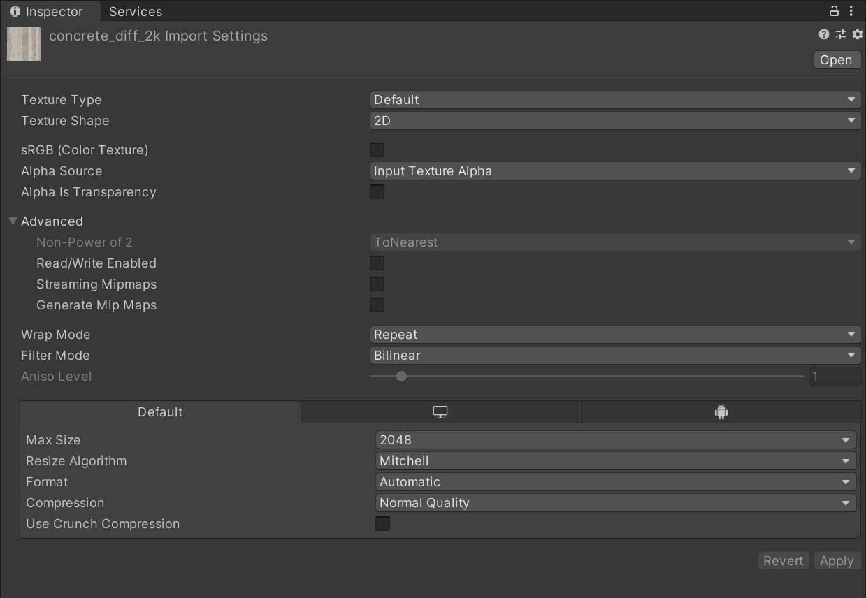
Image Inspector
“Default” is set as the texture “type” for all these maps. Yet we also have imported a normal map which is a distinct type of map. Thus select the normal map and set its type to “Normal map”. Any changes you make to these import settings have to be applied via the button in the lower right.
Now we can start to apply our textures to the material we created earlier. To apply a material to one of the channels, you can just drag and drop it onto the small square at the front of the entry.
The first input presented to us is “Albedo” and it defines how much diffuse light is reflected from a light source. Thus you will also hear the term “diffuse” used interchangeably with albedo. You can essentially think of it as the base color of the material. Albedo maps have a color box right next to them, this is an option to tint the object.
Let’s add the normal map next. Normal maps are super interesting. You will instantly see that they have a weird look to them. What they do is define the direction in which surface is supposed to face per pixel. They are used to adding fake detail to objects. They can also be used together with Height Maps. This will increase the effect even further.
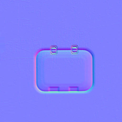
Part of a Normal Map
Occlusion Maps define how much indirect light your objects should receive. Because light can not be calculated accurately at run-time for such light sources, these pre-calculated maps will prevent from bringing light to areas that should not receive strong lighting. The “AO” map goes here as AO stands for “ambient occlusion”.
The next texture we can define is “metallic” and it defines what it says: how metallic the material will appear in the rendering. Why would you want to define that via map? Something is metal, or it isn’t, right? Well, think of a piece of metal that has some dirt on it. The plate is metal, the dirt isn’t and thus it should not reflect like metal. That’s why we can define metallic via a texture as well
But right now we might have a problem. We don’t have any metallic maps in our texture set. They way PBR is set up in different applications differs and so do these texture sets. The easiest fix for now is to change the shader for our material. Click on the drop-down at the top and select the Autodesk Interactive Shader. This one is set up for all the maps we actually have in our texture set.
If you check the box for Emission, you can also define a texture with information for which parts of the mesh should emit light.
Now with a material set up, let us create a new scene and a plane inside of it. Apply the material to the plane.
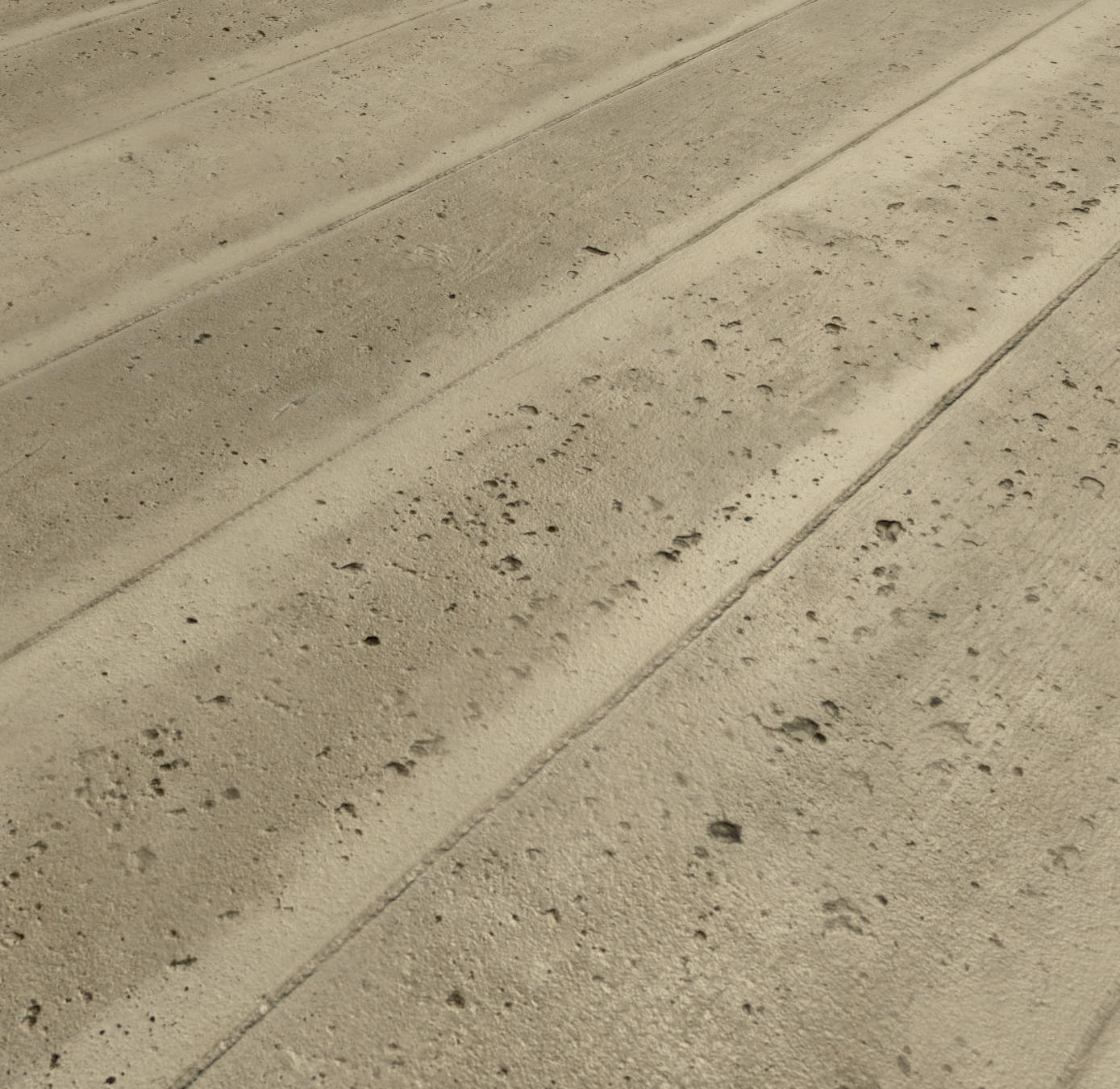
Concrete rendered in Unity
There isn’t really anything spectacular, but textures can do so much to the look of your scenes. Thus we can make something quite different out of our simple sketches we did earlier.
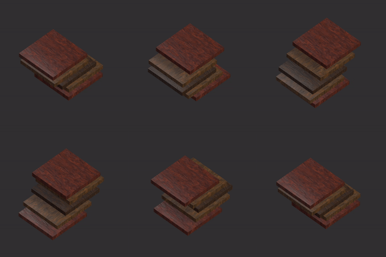
Cuboids with applied Texture
We will use more of this stuff once we get to lighting.
Render Textures
The Textures we have been using now are static images we import. But we can also produce Textures at the runtime of the application using “Render textures”. Render Textures are created by actually rendering the scene with a camera and then using the rendered result as a texture. They can be used like any other texture. You could use them to create effects like portals to other worlds. They are also useful to create things like streaking effects.
The first step is to create a RenderTexture in the Project View. On the RenderTexture, you can define the resolution you want your texture to render. For simple scenes you can pump this up, but in more complex scenes this might add harshly to your performance. We also need a camera that renders to that RenderTexture. Create a camera, and in the inspector drag and drop your texture into the Render texture slot. Now you can drag the Texture onto any Gameobject in your scene and you will see the picture recorded by that camera on it.
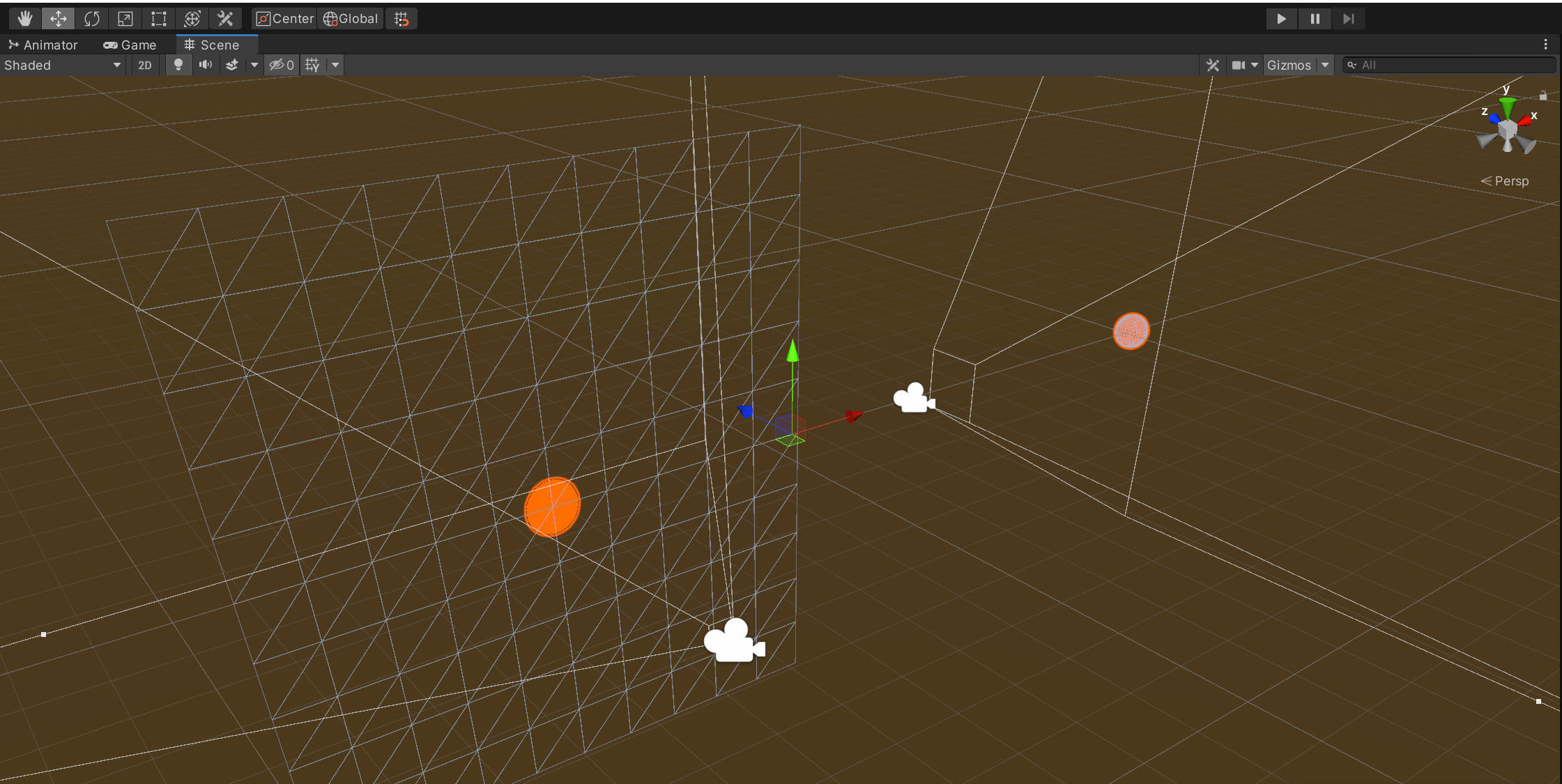
The right Camera is filming the sphere, the result is displayed on the plane to the left
But now both cameras render the same scene. We can adjust this using Render Layers. All objects in Unity reside on a specific Layer. Usually this is the “Default” Layer. How appropriate. But we want to render some images in the default layer and other in the render texture layer. To create a new one, just select the Layer drop-down menu on any object.
The last entry in the listis for adding a new layer. All objects you want to render exclusively in your RenderTexture camera then need to be set to this layer. On the RenderTexture camera itself you need to adjust the “Culling Mask”. The culling mask is by default set to everything, but you can also supply it with a specific layer.
We can also adjust the “Camera Flags”. If you set this to “Don’t Clear” or “Depth Only”, the Render Texture will contain the image you rendered just the frame before. Objects visible in the camera will then only overwrite the pixels in which they are visible. Using this technique, we can recreate some things you might have seen in some Processing sketches. The scripts for these luckily are really rather easy. All materials we use are Unlit again, the same shader we used for our Cuboids.
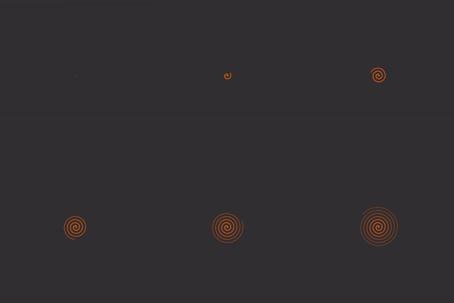
Spiral
You probably realized that we don’t really need to use Render Textures to achieve these results. But we can use them to so replicate the rendered result and create symmetrical creations using these.

Spiral
But we can do even more fun things with textures. We can even manipulate them or create new ones at runtime. If you want to manipulate a texture, it has to be “Read/Write Enabled” in the inspector. You can then use GetPixels() to get an Array of Colors. Now remember, your typical Full HD Image has slightly over two million pixels. Reading those in, manipulating them and sending them back to the GPU won’t probably happen in 60 Frames per Second. Thus for real-time updates this only works for small textures.
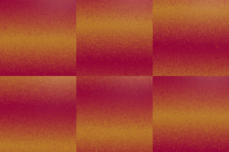
Animated Texture
But let us dive into the code:
AnimatedTexture.cs
We start with a Gradient which we will roll through over time using the gradientIterator. We then also create an Array of Pixels and a Texture2D. We initialize both the Pixels Array and the new Texture Array to 128x128 Pixels. For the pixels we use the GetPixels() method to make sure we use the same color space as any new Texture.
Then each frame we call the GenerateNewPixels() method. In it we create an evaluation point for the Gradient and a random number. If the random number is higher than a certain threshold, we update the pixel. Back in the main Update loop we apply the texture.
The random number leads to the pixelization effect along the moving gradient. You can play with the threshold to adjust the strength of it.
As stated earlier, you will quickly run into performance issues on larger images. But, we can still do fun things with these, as we can just do smaller chuncks of operations per frame. Say, change one pixel or a bunch of them at a time. A common technique for this is pixel sorting. This way we can arrange pixels by Hue, Saturation or value along the array.
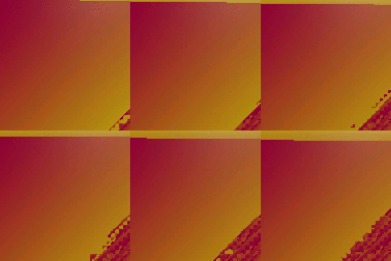
PixelSorting
PixelSorting.cs
Additional Resources
Textures and Texture Toolkits - some paid some free: